Learn how V-bending works, the differences between air bending, bottoming and coining, how to select the correct V-die opening, estimate inside radius and calculate press-brake tonnage.
V-bending is one of the most widely used sheet-metal forming processes. From electrical enclosures and brackets to machine frames and structural components, countless fabricated parts rely on accurate press-brake bending.
But getting a good bend is not simply a matter of selecting a punch and pressing the material into a V-die.
The bending method, die opening, material thickness, inside radius, flange length and required press force all influence the final result.
In this guide, we will cover the three common V-bending approaches— air bending, bottoming and coining—and explain how to select the V-die and estimate the required bending tonnage.
What Is V-Bending?
V-bending uses a V-shaped lower die and a punch to deform a sheet-metal blank into an angled shape.
The basic setup consists of:
- Punch: The upper tool that pushes the sheet downward.
- V-die: The lower tool supporting the sheet.
- Sheet thickness (T): Thickness of the material being bent.
- Die opening (V): The distance across the V-die opening.
- Inside radius (IR): Radius formed on the inside of the bend.
- Bending angle: The final angle of the formed part.
The relationship between these parameters determines the amount of force required and the resulting bend geometry.
The Three Main V-Bending Methods
There are three commonly discussed methods of forming a V-bend:
- Air bending
- Bottoming
- Coining
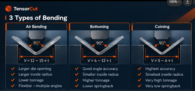
The key difference is how far the punch travels into the V-die and how much contact occurs between the tooling and the workpiece.
1. Air Bending
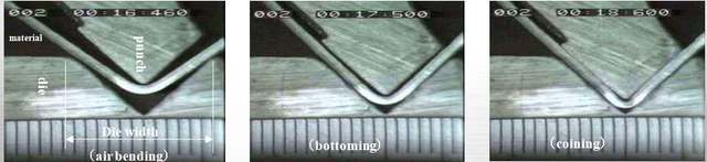
In air bending, the sheet does not completely conform to the shape of the punch and die.
The punch presses the material into the V-die, but there remains a gap between the sheet and the bottom of the die.
Only the outer edges of the sheet are in contact with the die.
This makes air bending particularly flexible because a single punch and die combination can produce multiple bend angles by changing the punch depth.
Typical Air-Bending Characteristics
| Parameter | Typical guideline |
|---|---|
| V-die opening | ~12–15 × T |
| Inside radius | ~2–2.5 × T |
| Angle accuracy | Depends strongly on material and setup |
| Required force | Relatively low |
| Flexibility | High |
For example, when bending a 2 mm sheet using a V-die around 24–30 mm wide, air bending can produce a range of angles without changing the tooling.
This flexibility is one of the biggest reasons air bending is widely used in production.
2. Bottoming
In bottoming, the punch drives the sheet much further into the V-die until the material comes into substantially greater contact with the die surfaces.
Compared with air bending, bottoming generally provides:
- Better angular consistency
- Lower springback
- More repeatable bend geometry
- Higher required tonnage
Typical die openings are smaller than those commonly used for air bending.
Typical Bottoming Characteristics
| Parameter | Typical guideline |
|---|---|
| V-die opening | ~6–12 × T |
| Inside radius | ~1–2 × T |
| Angle accuracy | Good |
| Required force | Higher than air bending |
| Springback | Lower |
Bottoming can therefore be useful when tighter angular control is required.
However, the higher forming force means that machine capacity and tooling strength must be checked carefully.
3. Coining
Coining takes the forming process further.
The punch penetrates into the material and forces the sheet into close conformity with the punch and die geometry.
This produces very accurate bends with significantly reduced springback.
Typical Coining Characteristics
| Parameter | Typical guideline |
|---|---|
| V-die opening | ~5–6 × T |
| Inside radius | ~0.5–0.8 × T |
| Angle accuracy | Very good |
| Required force | Very high |
| Springback | Very low |
The major disadvantage is the required force.
Coining can require several times more tonnage than air bending, so it should not be selected simply because it provides excellent angular accuracy.
Air Bending vs. Bottoming vs. Coining
The three methods can be summarized as follows:
| Feature | Air Bending | Bottoming | Coining |
|---|---|---|---|
| Typical V opening | 12–15T | 6–12T | 5–6T |
| Typical inside radius | 2–2.5T | 1–2T | 0.5–0.8T |
| Tool/workpiece contact | Low | High | Very high |
| Required tonnage | Low | Medium | Very high |
| Springback | Higher | Lower | Very low |
| Angle accuracy | Good with compensation | Good | Excellent |
| Flexibility | Excellent | Moderate | Lower |
| Tool/machine loading | Lower | Higher | Highest |
These values are guidelines rather than universal rules. Actual results depend on material grade, tensile strength, tooling geometry, machine condition and bending setup.
Selecting the V-Die Opening
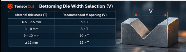
The V-die opening is one of the most important decisions when preparing a bending operation.
A common starting point for bottoming is:
| Sheet thickness T | Recommended V opening |
|---|---|
| 0.5–2.6 mm | 6 × T |
| 3–8 mm | 8 × T |
| 9–10 mm | 10 × T |
| ≥12 mm | 12 × T |
For example, consider a 3 mm sheet.
Using the guideline above:
V = 8 × T
Therefore:
V = 8 × 3 = 24 mm
A 24 mm V-die would be a reasonable starting point for the bottoming operation.
The final tooling selection should still be validated against the material, machine and tooling manufacturer's recommendations.
Inside Radius and V-Die Width
The die opening also has a strong influence on the resulting inside bend radius.
For bottoming, a commonly used approximation is:
where:
- IR = inside bend radius
- V = V-die opening
For example, with a 24 mm V-die:
IR ≈ 24 / 6 = 4 mm
This relationship is useful during early design and quoting because it allows engineers to estimate the expected bend radius before the actual tooling is selected.
However, the actual inside radius can vary with material strength, thickness, tooling geometry and bending method.
Minimum Flange Length
Another important design consideration is the minimum flange length.
A useful starting guideline is:
where:
- b = minimum practical flange length
- V = die opening
For a 24 mm V-die:
b ≈ 0.7 × 24 = 16.8 mm
So a flange shorter than approximately 17 mm may become difficult to form reliably with that particular die.
This is especially important when designing small brackets, tabs and folded edges.
If the flange is too short, the sheet may not be adequately supported by the die shoulders, resulting in deformation or inconsistent bending.
How Much Tonnage Does a V-Bend Require?
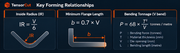
Press-brake tonnage is another critical consideration.
A simplified empirical relationship for V-bending is:
where:
- P = required bending force, tonnes
- L = bending length, mm
- T = material thickness, mm
- σb = material tensile strength, kgf/mm²
- V = die opening, mm
- C = empirical correction factor
The training reference uses:
C = 1.5
σb = 45 kgf/mm²
Substituting these values gives the simplified relationship:
Therefore:
This is a useful quick-estimation formula for preliminary process planning. The above formula is considering material as Mild Steel. Multiply by 0.5 when employing Aluminium and multiply by 1.5 when employing Stainless Steel.
Example: Calculate Bending Tonnage
Suppose we need to bend:
- Material thickness = 3 mm
- Bending length = 1 metre
- V-die opening = 24 mm
- Material tensile strength ≈ 45 kgf/mm²
Using:
P = 68 × T² / V
we get:
P = 68 × 3² / 24
P = 68 × 9 / 24
P ≈ 25.5 tonnes/metre
Therefore, the estimated bending force is approximately:
25.5 tonnes for a 1 m bend
For a 500 mm bend, the estimated force would be approximately half:
12.75 tonnes
Bending force increases linearly with bending length but approximately with the square of material thickness.
What Does the Tonnage Formula Tell Us?
The equation provides several important design insights.
1. Longer bends require more force
If the bending length doubles, the required force approximately doubles.
This is why a 2 m long bend requires approximately twice the tonnage of a 1 m bend, assuming all other variables remain constant.
2. Stronger materials require more force
Higher tensile strength increases the required bending force.
For example, bending stainless steel generally requires more force than bending a comparable thickness of mild steel.
3. Thickness has a major effect
Because thickness is squared:
Increasing sheet thickness from 2 mm to 4 mm does not merely double the required tonnage.
It can increase the theoretical force by approximately:
(4/2)² = 4×
This is why even relatively small increases in material thickness can have a substantial impact on press-brake capacity.
4. Larger V-die openings reduce force
The formula shows an inverse relationship with die opening:
Increasing the V opening generally reduces the required force.
However, using an excessively large die opening can increase the bend radius and affect flange geometry and dimensional accuracy.
Tool selection is therefore a balance between tonnage, radius, geometry and accuracy.
Press-Brake Capacity Matters
As a practical rule, the calculated bending force should not simply be compared with the nominal machine tonnage without considering the actual setup.
Before production, verify:
- Press-brake rated tonnage
- Available tonnage at the required stroke
- Tooling load capacity
- Die opening
- Punch geometry
- Material thickness
- Material tensile strength
- Bending length
- Number and location of bends
- Machine frame/load distribution
The training reference also notes a typical press-brake applicability around 1 ton/cm of bending length, equivalent to approximately 100 tons/m, with higher loading possible in exceptional cases.
These should be treated as machine- and application-specific limits rather than universal design rules.
Why V-Die Selection Matters in CAD Design
V-die selection is not just a manufacturing concern.
It affects the actual geometry of the finished component.
The die opening influences:
- Inside bend radius
- Minimum flange length
- Bend allowance
- Overall part dimensions
- Required tonnage
- Springback
- Angular accuracy
- Tool interference
This means that designing the flat pattern without considering the intended bending process can create manufacturing problems later .
For production-ready sheet-metal design, the CAD model, bend allowance, tooling and manufacturing process should be considered together.
Practical Design Checklist for V-Bending
Before releasing a sheet-metal component for fabrication, check the following:
Material
- What material grade is being used?
- What is its thickness?
- What is its tensile strength?
- Is the material prone to high springback?
Bend Geometry
- What is the required bend angle?
- What inside radius is required?
- Is the flange long enough?
- Are there nearby holes, slots or cutouts?
Tooling
- What V-die opening will be used?
- Is the punch compatible with the required radius?
- Can the tooling handle the required force?
Machine
- Is the press brake rated for the calculated tonnage?
- Is the bending length within machine capacity?
- Is the load appropriately distributed?
Manufacturing
- Will air bending, bottoming or coining be used?
- Has springback been considered?
- Is the required angular tolerance realistic?
- Does the selected process match the production volume?
Final Takeaway
V-bending looks simple, but reliable bending requires the interaction of material, thickness, die opening, bend radius, tooling, machine capacity and process selection .
For most general-purpose fabrication, air bending provides an excellent combination of flexibility and relatively low tonnage. Bottoming can be considered when improved angular consistency and reduced springback are required, while coining provides very high accuracy at the cost of substantially higher forming forces.
As a quick starting point:
- Air bending: approximately 12–15T V-opening
- Bottoming: approximately 6–12T V-opening
- Coining: approximately 5–6T V-opening
For bottoming, a useful starting estimate is:
And for preliminary tonnage estimation using the material assumptions discussed above:
These formulas are best used for initial design, quoting and process planning. Final production parameters should always be validated against the actual material specification, tooling manufacturer's recommendations and press-brake capacity.
At TensorCut, understanding these manufacturing relationships is essential to turning a digital sheet-metal design into a part that can be produced accurately, consistently and cost-effectively.
Design for manufacturability starts before the first bend.